Clock synchronisation in systems communication

Motive

Starting with that, Guide to implementing a Clock synchronisation algorithm on low power wireless sensor networks.

following will be some pointers and papers to read before wandering in the wild to get things done and reinventing the wheel.

Literature survey

  • Message Time-stamping in Sensor Networks
  • Flooding time synchronisation protocol [1]
    • this protocol is very good in terms of single of time synchronisation
    • it uses linear regression, get ready to do some compute on your MCU
    • very good numbers and explanation in those slides [2]
    • Global Clock Skew
  • for multi-hop networks, this one is a good paper to read
  • Temperature Compensated Time Sync [4]
    • The only requirement on that time synchronization protocol is that it can calculate the current frequency error with respect to the reference node’s clock. Unlike other time synchronization protocols, TCTS also records the current temperature during a synchronization exchange. Both the temperature and frequency error at the end of the synchronization exchange is cached in a frequency vs. temperature table in memory. [5]
    • Before attempting subsequent resynchronization, TCTS will measure the current temperature and consults its internal calibration table. If the current frequency error for the measured temperature is cached, TCTS will not attempt to resynchronize with the reference node since a new time estimate is not required. Eventually, when all of the operating temperatures have been observed, TCTS will have auto-calibrated the low-stability clock, essentially providing a TCXO timebase. [5]
    • In addition, since we know that the curve should fit a quadratic function of the form

      fe(T) = −A · (T − T0)2 + B,

      where A is the temperature coefficient, T0 = 20◦C represents room temperature, and B is a frequency error offset, we can fit the measured calibration points to this curve and obtain frequency error estimates for previously unobserved temperatures, thus drastically improving the range and accuracy while eliminating a factory calibration step and allowing on-demand calibration. [5]

  • Virtual High-Resolution Time (VHT) [5]
    • basic idea behind VHT
        • During active periods, the high-frequency clock is turned on, and a hardware counter counts the number of high-frequency clock ticks that occur during each low-frequency clock interval, i.e., there are high-frequency clock ticks during each low-frequency one.

          φ0 = fL / fH

        • At the time of the event, the system records not only the value of the counter sourced by the low-frequency clock but also the value of the counter sourced by the high-frequency clock which was reset at the end of the most recent clock tick of the low-frequency clock. Thus, this second timer will indicate the phase φ within a low-frequency clock tick, allowing an effective resolution to be up-sampled to the high-frequency clock (modulo one cycle of jitter). The event time is sampled as

          tevent=CL ·φ0 +φ.

        • While the high-frequency clock is not phase-locked with the low-frequency clock, the phase error is limited to < 1/fH, and thus is of the same order as the quantization error.

Implementation of VHT in microcontrollers

The requirement is quite simple and the target chipset used in this project has additional two timers.

  1. 2 clocks driven by two oscillators
  2. 2 timers with capture and compare modes.

The Capture mode which will retrieve a timer value based on a signal event.

The Compare mode which will constantly monitor a timer counter value and compare it to a value set in the application. When they match, it will trigger an event.

The target implementation is on CC1350 chipset [6]. They have Four General-Purpose Timer Modules (Eight 16-Bit or Four 32-Bit Timers). With newest hardware revision CC1352r, almost same chip can be used to run Bluetooth 5.0. This has a M4 instead of a ARM M3 processor. This optimization with the increase in the memory footprint can be attributed to the new Bluetooth 5.0 standard.

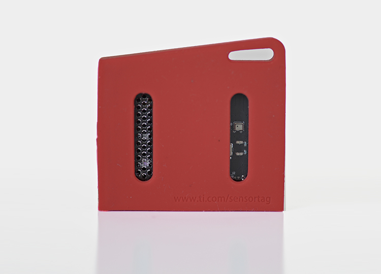
The application framework used will be Contiki-OS [7]. I will use the latest version that is on development which also supports the SensorTag board and the launchpad [8]. A toolchain setup and compilation of the Contiki-OS is done in this post.

Illustration of the Virtual High-resolution Time event time-stamping mechanism on a micro- controller [5].

The two capture are connected to the event. The paper expects to make the interrupt for start of the frame delimited (SFD) which is previously justified for better resolution on clock synchronisation in figure 2 [5].

An additional capture unit on the fast timer captures the counter on every low frequency rising edge. As the Sync event, where the value of h0 is stored in one of the capture units. Later, when the SFD line rises, the two capture units on the two timers store l0 (the value of the low-frequency counter) and wh1 (the value of the high frequency counter), respectively. Using these three captured values, the event time can be calculated as

tevent=l0·φ0+(h1−h0) modφ0.

Counter overflows are an issue to be tackled. Overflows of the high-frequency counter are not a problem since they run only on a short burst when the system is synchronising / listening for packet. The low-frequency clock must have a counter width of 64-bit since 32-bit counters will overflow by 5 minutes since the low-frequency counters are used for long intervals.

As per the suggestion on [5] a 32KHz and 8MHz clocks are used for the timers. The MCU has Clock Speed up to 48-MHz.

References:

[1] http://www.isis.vanderbilt.edu/sites/default/files/Maroti_M_11_3_2004_The_Floodi.pdf

[2] https://www.tik.ee.ethz.ch/file/5562ed988ca095af8331114dd81c6c70/sensys09_slides.pdf

[3] https://people.mpi-inf.mpg.de/~clenzen/pubs/LSW09optimal.pdf

[4] https://ieeexplore.ieee.org/document/5170185/

[5] https://web.eecs.umich.edu/~prabal/pubs/papers/schmid10vht.pdf

[6] http://www.ti.com/lit/ds/symlink/cc1350.pdf

[7] http://contiki-ng.org/

[8] https://github.com/contiki-ng/contiki-ng/wiki/Platform-srf06-cc26xx


Compiling Contiki for CC1350

Setup:

  • macOS 10.13.5
  • VM – VirtualBox
  • Guest OS: Ubuntu 16.04

Setup Contiki on the local machine:

Install the following packages. you might need sudo right.

# sudo apt-get remove gcc-arm-none-eabi gdb-arm-none-eabi binutils-arm-none-eabi
# sudo add-apt-repository http://ppa:team-gcc-arm-embedded/ppa
# sudo apt-get update

Compile Contiki hello-world for Native:

Native means that your code will compile and run directly on your host PC.
for me, it will run on the Ubuntu 16.04 OS on the VM.

cd into your development folder.

# git clone https://github.com/contiki-os/contiki
# cd contiki/examples/hello-world
# make TARGET=native
mkdir obj_native
  CC        ../../core/ctk/ctk-conio.c
  CC        ../../platform/native/./contiki-main.c
  CC        ../../platform/native/./clock.c
  CC        ../../core/dev/leds.c
### output truncated ###
  AR        contiki-native.a
  CC        hello-world.c
  LD        hello-world.native
rm hello-world.co

The target command tells the compiler to compile for the current system.
This is what is later changed for cross compiling to our target platform.

Type the following command to run the hello-world program.

# ./hello-world.native
Contiki-3.x-3343-gbc2e445 started with IPV6, RPL
Rime started with address 1.2.3.4.5.6.7.8
MAC nullmac RDC nullrdc NETWORK sicslowpan
Tentative link-local IPv6 address fe80:0000:0000:0000:0302:0304:0506:0708
Hello, world

if this is how it worked! your compilation worked!

Compiling Contiki-OS for CC13xx

The only thing to be changed is the target. make clean is an important step.

make clean
make TARGET=srf06-cc26xx BOARD=sensortag/cc1350

this says the compilation works if you see the following:

CC ../../cpu/cc26xx-cc13xx/lib/cc13xxware/startup_files/ccfg.c
CC ../../cpu/cc26xx-cc13xx/./ieee-addr.c
AR contiki-srf06-cc26xx.a
CC ../../cpu/cc26xx-cc13xx/./fault-handlers.c
CC ../../cpu/cc26xx-cc13xx/lib/cc13xxware/startup_files/startup_gcc.c
CC hello-world.c
LD hello-world.elf
arm-none-eabi-objcopy -O ihex hello-world.elf hello-world.i16hex
srec_cat hello-world.i16hex -intel -o hello-world.hex -intel
arm-none-eabi-objcopy -O binary --gap-fill 0xff hello-world.elf hello-world.bin
cp hello-world.elf hello-world.srf06-cc26xx
rm hello-world.i16hex hello-world.co obj_srf06-cc26xx/fault-handlers.o obj_srf06-cc26xx/startup_gcc.o

This error absolutely means that the installation of the compiler for cross-compilation wasn’t successful.

/bin/sh: 1: arm-none-eabi-gcc: not found

Next step would be to compile with contiki-ng since, there is active development is happening there and to base all developments to that repo.

# git clone https://github.com/contiki-ng/contiki-ng
# cd contiki-ng
# git submodule update --init --recursive

navigate to the hello-world example and hit the following

# make clean make TARGET=srf06-cc26xx BOARD=sensortag/cc1350

References:

[1] https://sunmaysky.blogspot.com/2015/08/setup-6lbr-to-run-6lowpan-with-cc2531.html

[2]https://sunmaysky.blogspot.com/2015/09/contiki-subg-hz-6lowpan-on-cc1350.html

DNSed: A simple useable internet name for large scale IoT

Intent

When there is a city wide Wireless Sensor Network (WSN), this has to be resolved with anything meaningful, say name of where it is located. then this has to be the name that it should be resolved to.

to creat DNSed, as in past tense in English for DNS. To DNS the shit out of the IoT. To create an amazing network and to overload the DNS servers. To create everything out in the open, so everything in the Hollywood movies can come true.

Scenario

  • When a water tank level indicator at place called “Meereen”.
  • There is a number for the water tank which is 256.

then, this can be described in the internet nomenclature as

  • domain name: meereen.got
  • object: water tank
  • number: 256
  • sensor type: level indicator

this would translate to an internet name of “level.256.water.meereen.got”

usually, there is only a sensor in a an area and they are organised in cluster.

in that case, Meereen’s water tank is being referenced, and the sensor 256 is being addressed where the level is being asked for, https://256.water.meereen.got/level where level is a service provided by the sensor


Possibility:

It is possible to use BIND9 to build a DNS server, then create the zone records to point to the different sensors. the tutorial gives a good insight on deploying a BIND9 DNS server [3]. There are very good python libraries available in such an instance to build an DNS server and then work with their API. The following are some interesting DNS APIs for python to process DNS records on server.

[1] http://www.dnspython.org

[2] https://pypi.python.org/pypi/easyzone/1.2.1

Implementation:

In this effort, the implementation takes advantage of the REST API provided by DigitalOcean to make the DNS. as the idea is to create a very dynamic name resolution for IoT devices and this does not involve building a DNS server from scratch. The DNSed will be a library that will used in the IoT devices as well to communicate to the central server which will be further proxied to the DNS Server of DigitalOcean. This architecture would provide a method to have a better security by not distributing the API keys throughout the network on every device.

The functional block diagram below tries to describes this exact architecture

drawit-diagram-2

References:

[1] http://www.dnspython.org

[2] https://pypi.python.org/pypi/easyzone/1.2.1

[3] https://www.digitalocean.com/community/tutorials/how-to-configure-bind-as-a-private-network-dns-server-on-ubuntu-14-04

[4] https://developers.digitalocean.com/documentation/v2/#domain-records

[5]
drawit-diagram-1

SensyLight: sensible atmosphere using Internet of Things

https://vimeo.com/192196471

The above video is from a research lab at the MIT Media Lab called Responsive Environments. They have a really interesting article [1] about a multimodal mediated work environment.

Internet of Things has been of great buzz these days. It is interesting, but why is it interesting? Just made a project/home lighting on this project.

So, here is the scenario for the internet of things. The thing in the Internet of Things is the web controlled lights – LED strip. The “control” part of the lights is managed by the Arduino. The task of Arduino would be to “GET” data that matters and send that info to the light strip. The ways in which the LED strip can be manipulated from the Arduino can be listed as

  • 1 LED can have 3 inputs, R G B.
  • Each R G B can value from 0 – 255 which is 256 values.
  • There are 32 LEDs in the strip.

Which makes a lot of math and logical decisions for the Arduino to handle. That is the whole point of networking these devices, now they have access to on-demand computing resources. This means we need the medium to connect the Arduino to the internet. That is done using the WiFi module which communicates with the Arduino using USART communication.

There are two ways to handle the information flow:

  • To directly to give out RGB information an hour
    • A lot of data transfer between the devices, but all of the computing, the decision is taken care of by the remote server
    • the device is highly dependent on the connection for operation
  • To query the server for Sunlight information (sunrise and sunset) and compute the colour information.
    • Having an update system to change the “compute” algorithm makes it highly robust.
    • Gets information for a day / a week and then “compute” with the algorithm. Also, listen for any settings like
      • Party lights
      • Work lights
      • get back to sunlight operation

Tools used:

Low cost, easy implementation of mediated atmospheres, to make your apartment to provide sensible lighting that can help harmonize the body and mind with the circadian rhythm.

[1] 17161.JosephA.Paradiso.Preprint1.pdf

[2] 192196471

Multi-threading in Python: A quick guide for python multithreading

All the resources for multi-threading python programming.

import threading

Thats all is there in python multi processing! Of course you should know what to use where? I found this great slideshare option that you should go through to get up and running in python multi processing. An Introduction to Python Concurrency.
Semaphore is the oldest parallel processing concepts. Which of course highly useful for any multi processing programs. For me it was a SPI Bus accessed using a raspberry pi. There are 4 chip selects and each communication event is a new thread. To provide access to a single bus, semaphore was used. Its implementation is straight forward in python.

parallelProc = threading.Semaphore(1) #parallelProc is the object that holds the semaphore and allows only one concurrent process.

now, it might get painful to get the acquire and release right, but otherwise it is great!

def communicationEvent():
parallelProc.acquire()
print 'Doing bus transactions here!'
parallelProc.release()

Finding time for adding more of the concepts in the future
One might think life just got easier with multi-threading, but thats when shit gets real! (Ned Stark way of telling)

Installing MEAN stack for Fullstack application development

The best one liner for what MEAN stack is given in the following picture.Screen Shot 2015-01-18 at 22.48.40

MEAN stack is more like LAMP.

M = MongoDB

E = ExpressJS

A = AngularJS

N = NodeJS

MEAN Stack Logo

There has been a lot of development from Google for the AngularJS and NodeJS. They are minimalistic and javascript based, for now cutting edge web development tools.

For installing MEAN stack in ubuntu, follow the commands to set up your MEAN Stack. I deployed my server in Digitalocean which is like my obsessed service for cloud deployment.

Install MongoDB
#~ sudo apt-get install mongodb
Install NodeJS and Npm
#~ sudo apt-get install nodejs npm
and create a symlink
#~ sudo ln -s /usr/bin/nodejs /usr/bin/node
Install Bower
#~ sudo npm install -g bower
Install Grunt
#~ sudo npm install -g grunt-cli
Install MEAN
sudo npm install -g mean-cli
Init your first App
$ mean init testApp
type in your IPaddress with port 3000
http://xxx.xxx.xxx.xxx:3000

Testing Contiki-os with the first program using CC2530 / CC2531

This is not going to take too long for you to test your first Contiki program which will enable you to test your environment setup and also to understand the procedure of development using Contiki-os for the target chips CC2530 and CC2531. Continue reading “Testing Contiki-os with the first program using CC2530 / CC2531”

Generating Heat Maps for eye-tracker data

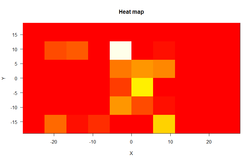
Heatmap generated for the userXX

A heat map is a graphical representation of data where the individual values contained in a matrix are represented as colors. –Wikipedia

 Concept

Here is my approach to deal with it. All that is need is a frequency of a value being repeated in case of one dimension and then creating a color  map for high to low and plotting them on a graph. Continue reading “Generating Heat Maps for eye-tracker data”

TI CC2530DK – Contiki OS – Internet of Things

This blog post is an effort to create a one stop information for starting off your Contiki project with cc2530DK.

There is enough information already available on Github wiki. This post is more than an extension to have all information under one place and as usual my way of documenting my projects!

Continue reading “TI CC2530DK – Contiki OS – Internet of Things”

WiFi Positioning System – Using Python and Google Geolocation API

I consider there is these following steps involved for such a program.

I will keep this as a documentation as well as a progress report to keep track of the project.

  1. Reading all the required information
    1. Reading SSID in MAC
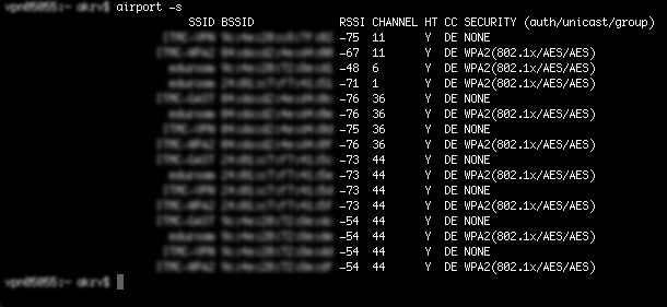
      • Using Airport Shell command
      • Here is how it should look: [viraldownloader id=180]
    2. Reading SSID in Linux (Ubuntu), Windows
      • identify shell command for linux/Ubuntu
      • identify shell command for windows
  2. Parsing them in JSON format
    1. Parsing information into required information into prescribed format
  3. CURL and Get the Location information in JSON
  4. Parse it and display on google
  5. Building a GUI

Here is the gitHub repository for the project that I am working on.

https://github.com/akrv/pyWPSLocalisation

Feel free to contribute/contact it is interesting for you aswin[at]southpaw.in